The waste heat recovery technology has been tested by these five different prototypes with different variations in power electronics, thermal collector contact surfaces, cooling system and the thermoelectric generators to configure the best option for each type of heat source.
Efficiency is one of the main parameters analysed in each project. This parameter shows how much energy is extracted from waste heat.
The efficiency of the prototype depends on the heat source, the heat collector type and the cooling system applied.
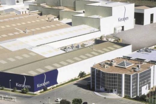
DISTILLER treats and manages industrial waste using distillation processes to recover solvents and treat contaminated aqueous solutions.
Thermal oil is used to supply the necessary heat to perform the distillation processes. Thus, the factory has thermal oil boilers to heat and recirculate the oil to different energy consumers through a close circuit.
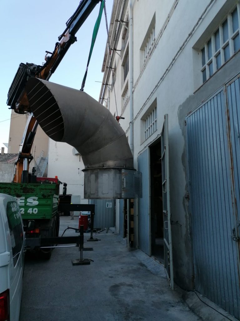
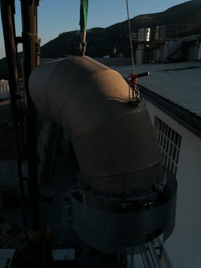
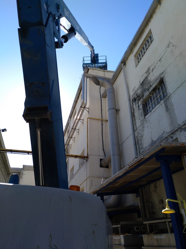
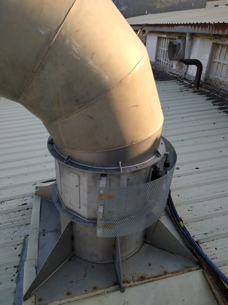
The energy recovery system (Heat R-System) installed in industrial waste manage plant that Distiller has in Sta. Perpetua de la Mogoda (Barcelona) makes use of the waste heat generated in a WOGA thermal oil boiler.
The operating cycle of the dryer is 24 hours a day, 7 days a week, and the gas temperature varies from 130 to 220 ºC. The device must withstand ambient temperatures up to 40 ºC and sun exposure.
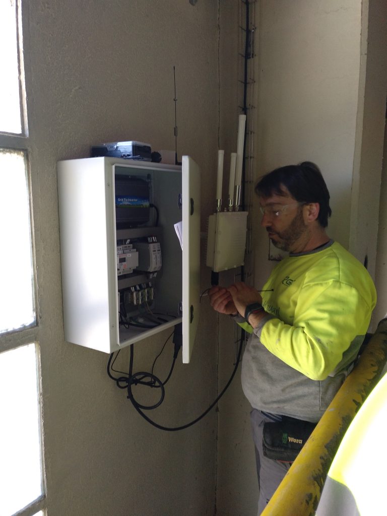
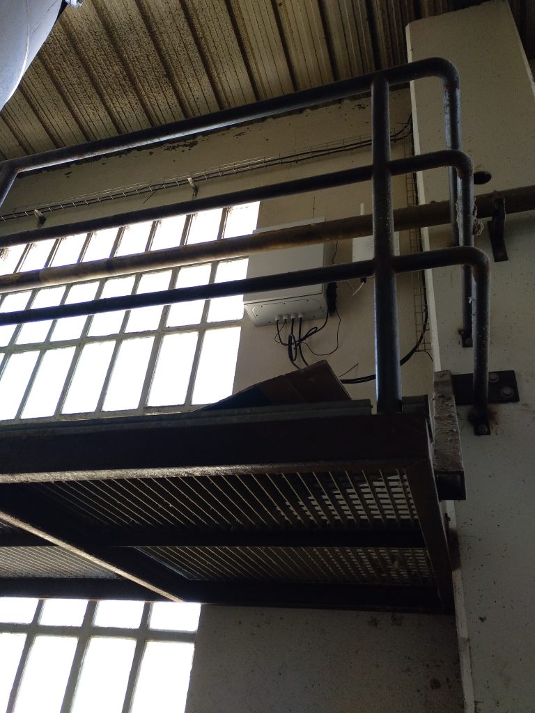
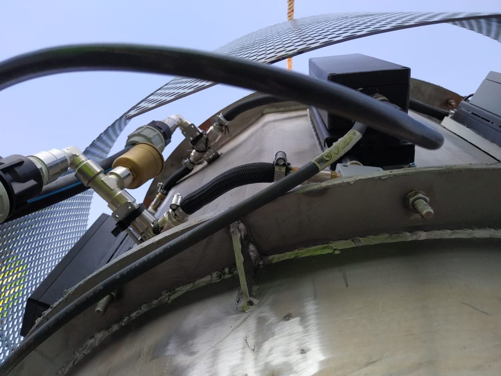
The recovery system that is installed is intrusive: the fins of the WHRU thermal collectors are installed inside the chimney to capture the maximum amount of heat from the gases. Although intrusive, this system does not affect the operation of the boiler, as it does not cause any pressure drop or condensation.
WHRU modules uses water heat-exchanger (water-block) for their cooling to obtain the maximum temperature difference between the two sides of the Peltier cells. The water is pumped from a well. The water-cooling temperature is 25 ºC.
In this project, the energy recovery system is based on a new type of WHRU:
WHRU -WBCV200

- Cooling system principle: Forced water convention
- Cooling components Cold plate or water heat exchanger (waterblock).
- Heat capture system principle Forced air convection – gas exhaust.
- Thermal collector Intrusive convectional heat sink
- Electrical energy generator Thermoelectric generator TEG – Peltier cell
- Peltier cell number 36 cells 40 *40 mm
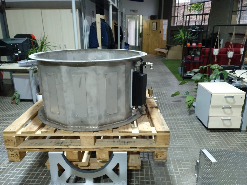
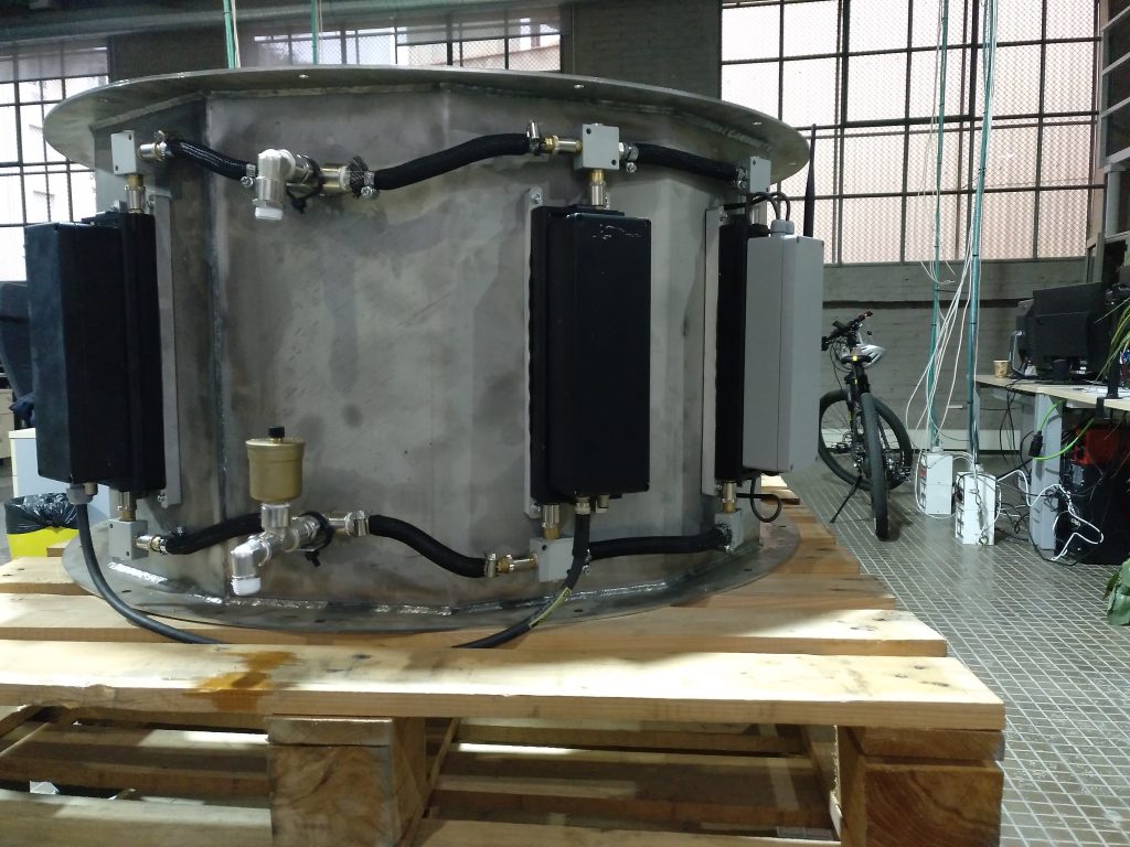
The main feature of this device is that it groups a set of 36 thermoelectric generators into a single unit. This design was created to group as many thermoelectric generators as possible in the smallest possible space, optimising the ratio of power generated per unit area.
Results
| Exhaust gas temperature | 130 – 220 ºC |
| Generation area of two WHRU. | 1705.7 cm2. |
| Mean power generated | *54.72 W |
| Maximum power generated | *96.50 W |
| Energy generated | *479.30 kWh/year |
| Power density | *565,80 W/m2 |
| Heat flow in the exhaust gas | |
| Heat flow through Heat R- System | *2275 W |
| Efficiency | 4.24 % |
This device shares many similarities with the Goma Camps prototype in terms of heat collection and cooling system, except that Distiller’s WHRU device packs more Peltier cells into a smaller area. In other words, Distiller’s WHRU device is equivalent to six Goma Camps devices.
The prototype developed for the Distiller’s project has the highest efficiency with a theoretical efficiency of around 4.24 %.
In this way, forced water cooling system together with forced convective flow heat collection based on the installation of the heat collector in contact with the hot gases is the best configuration for achieving the best performance of the prototypes.
This type of thermal collection uses a forced convective flow, which increases the temperature of the Peltier cells.
In addition, the power density of this WHRU device is increased by grouping 36 Peltier cells in a smaller area.
On the other hand, the action of the forced-water cooling system results in a significant temperature differential between the two sides of the Peltier cells which translates into a higher electrical power generation.
-From the standpoint of the installation, the water-cooling system requires a hydraulic loop with a pump. It is essential to ensure a continuous supply of cooling water to avoid damaging the prototype by exceeding the maximum working temperatures of the components. Therefore, installing two pumps instead of one or automating the start-up of the pump when the process starts are options to ensure the water supply. It is also crucial to ensure that all valves are open in the hydraulic circuit.
On the other hand, the quality of the water supply is important. The water must be free of suspended solids to avoid possible clogging that could hinder or prevent the water supply and thus damage the equipment.