
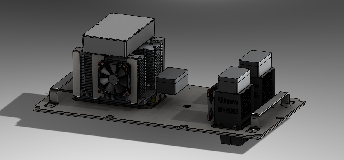
A Heat-R energy recovery station will be installed in a configuration of 3 WHRU modules, 2 with heat column system and a larger one with heat pipes.
The first system will consist of 4 40×40 thermoelectric cells and one fan and the second, consisting of 6 40×40 thermoelectric cells and 2 fans.
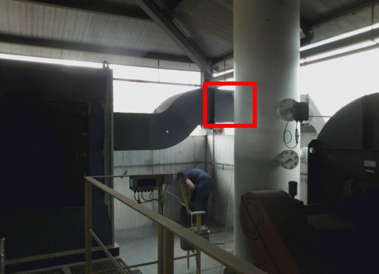
According to the result of the thermographic analysis, it is established that the combustion gas duct of the biomass boiler is the favorable point for the placement of WHRU units. For reasons of ease of installation, WHRU units will be located at the top of the rectangular flue gas outlet duct at its exit from the cyclone and before the exit of the boiler building duct to the bag filter.
The working cycle of the biomass boiler is 24 hours and the flue gas outlet temperature varies between 250-300 ° C depending on the fuel used, which may be strains and branches and/or forest masses. The ambient temperature is between 35-45ºC.
In the mechanical part, the previous version of WHRU has been modified by natural convection to forced convection to obtain greater performance. Said cooling system consists of heat pipes and fans. These heatsinks are entirely copper, so a protective paint against corrosion will be applied.
The fans will operate by PWM control in order to maximize the thermal differential to obtain greater performance in the thermoelectric cells.
The WHRU modules will penetrate the duct with aluminum heatsinks, so make a cut in the duct to accommodate the recovery station.
Each of the modules will have an integrated sensor to be able to measure the temperature of the hot and cold face of the cells; and a current sensor to measure the power generated. Said sensor refers to the name of nodes. 4 sensors are going to be installed:
• Node 1: 3 temperature sensors (cold face, hot face, gases)
• Node 2: 3 temperature sensors (cold face, hot face, gases)
• Node 3: 4 temperature sensors (cold face, hot face, two gases)
• Node 4 (output): Power generated
Mechanical design
According to the visit to the facilities of Bodegas Torres the following are data taken:
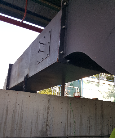
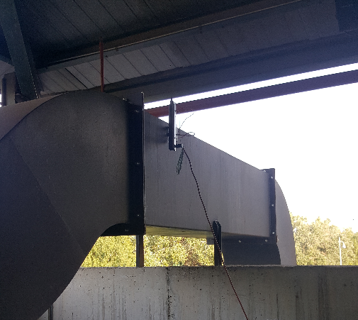
Section 1:
• Rectangular duct with a useful area of 570x950x580x4
• Undercover
– Gas temperature circulating inside the duct: 250ºC
– Flow rate: 1 m / s
– Ambient temperature: 32.9ºC
Due to the number of modules to be installed, it will not be necessary to remove the entire conduit, a cut will simply be made in the upper part of the conduit and a housing with our generation devices will be housed.
The solution adopted, the flat housing, will allow us to install three WHRUs. This component has a configuration in the form of “Sandwich” since it is formed by three pieces. Base housing, Insulator, Handle and Insulating support.
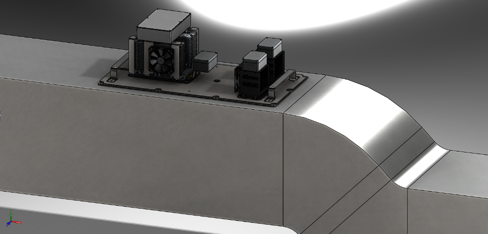
4 cells WHRU Module
This device is a forced air cooling system, where fan revolutions are controlled by a PWM system to maximize the thermal differential generator in the peltier cell.
The fan speed regulation will be controlled by the information provided by PT1000 sensors connected to an electronic board that governs all these operations.

This WHRU module consists mainly of the following components:
1. 90x90x70 aluminum sensor. With a normal anodizing to improve corrosion resistance.
2. Maco-Support cells – Mica Insulator. This component will act as a fixation to the mounting duct, and at the same time it will act as an insulator, since this material has 0.3 W / mK of thermal conductivity and will improve the performance of the equipment. In addition, it will serve to house the cells and refer them to their connections.
3. Power box support. Made of carbon steel. It will act as a support for the power box and will be placed on the Heat Pipe in order to prevent it from getting hot.
4. Heat Pipe Column. Cooling system with an operating principle similar to thermosiphon. Its objective is to transport heat from the hot zone to the cooling zone from a high pressure fluid, which in this case are the fins. It is made of copper and covered by an oxidation protection paint.
5. NOCTUA F12 fan. Industrial fan made of polyamide, and with IP67 environmental protection. Responsible for cooling the heat transported by the Heat Pipe and cooling the component.
6. Electronic box. Inside will go the electronic sensing, electronic regulation. The cells will enter directly. It is made of aluminum and is black.
7. Cells. The installation of 4 cells, model TGM-287-1,0-1,3 of Kryotherm with dimensions 40x40x3.6 mm that can produce up to 6.9 W. is decided.
In total, 2 modules of this type will be installed.
6 cells WHRU Module
This device also has a forced air cooling system, just like the 4-cell model. It will have two fans instead of one and also regulated by an electronics.
This WHRU, being more robust, houses the central box of the power electronics.
This WHRU module consists mainly of the following components:
1. 280x120x60 aluminum sensor. With a black anodized to improve corrosion resistance.
2. Maco-Support cells – Teflon Insulator. This component will act as fixation of the cells, and at the same time will act as an insulator, since this material has 0.25 W / mK of thermal conductivity and will improve the performance of the equipment.
3. Duct support frame. Stainless steel, its function is the fixation to the conduit.
4. Power box support. Made of carbon steel. It will act as a support for the power box and will be located at the bottom of the device.
5. Heat Pipe. Cooling system with an operating principle similar to thermosiphon. Its objective is to transport heat from the hot zone to the cooling zone from a high pressure fluid, which in this case are the fins. It is made of copper with aluminum and covered by an oxidation protection paint. It has 12 cooling tubes.
6. NOCTUA F12 fan. Two industrial fans made of polyamide, and with IP67 environmental protection. Responsible for cooling the heat transported by the Heat Pipe and cooling the component.
7. Central power box. Inside will go all the electronics that will manage the 3 generation modules.
8. Electronic box. Inside will go the electronic sensing, electronic regulation. The cells will enter directly. It is made of aluminum and is black.
9. Cells. The installation of 4 cells, model TGM-287-1,0-1,3 of Kryotherm with dimensions 40x40x3.6 mm that can produce up to 6.9 W. is decided.
In total 1 module will be installed.

Electronics design
The electronics consist of 2 parts: power electronics and sensorization.
The power electronics collect the voltage of each channel (the electronics are made up of 7 channels), and join the powers into a single output at 14V.The sensorization electronics have three functions:
- Monitor the temperature of the hot face, and the cold face of the modules.
- Check the fans used to cool the temperature of the Heat pipe. The speed of the fans should not be constant since it may be an unnecessary consumption, it is also interesting to prevent the cooling of the cold face from dragging (cooling) the hot face. For the 4-cell modules there must be 1 fan, and for the 6-cell module, 2 will be controlled.
- Monitor the temperature of the chimney gases with a PT100 sensor in the small modules, and with 2 PT100 sensors for the large module.
Power electronics
The power electronics of this project has some important evolution of our previous electronics:

Variable resistance
The variable resistor is a voltage divider composed of a fixed value resistor and a variable ohm resistor based on a MOSFET transistor, as shown in the following figure.

The variable resistance consists of two MOSFETs, connected to a control and measurement system. The function is to take current and voltage readings, power calculation, and send them via Bluetooth to the Gateway.
The control system by reading at the input of the variable resistor, offers a voltage at the output of the microcontroller to regulate the MosFETs in order to adjust the ohmic value of these, going down from the 14V output of the DCDC convertor to 13,65V, in order to obtain maximum power at the converter output.
Below, the block diagram of the full system:

Sensorization
One of the requirements of the project is the integration of temperature and current sensors in order to know the operation of the 3 modules.
Temperature
It is an electronic module located in each WHRU, it has the function of obtaining the measurements of the cold face and hot face temperature of the Peltier Cell and the gas temperature. We will use a PT100 sensors and the system will control the fan power.

Current
The meter consists of a HALL sensor plus the signal conditioner based on an integrated differential amplifier. The whole will be powered at 5V

Communication platform
The communications solution consists of nodes with sensors and gateway. The nodes will read the sensor data and using bluetooth technology they will communicate with the gateway. The gateway will act as a gateway receiving the data and sending it to the DAEVIS monitoring software.
